
What Is a Laser Diode? Comprehensive Technical Guide to Semiconductor Lasers, Working Principles, Design and Industrial Applications
Comprehensive Technical Guide to Semiconductor Lasers
Introduction
Laser diodes, also called semiconductor laser diodes, are the most widely deployed coherent light sources in modern optoelectronic systems. Unlike gas lasers, solid-state lasers or fiber lasers that rely on bulky gain media, laser diodes generate stimulated emission directly within a semiconductor PN junction. Their compact footprint, fast modulation bandwidth, high electro‑optical conversion efficiency and scalable output power make them irreplaceable for consumer electronics, automotive sensing, industrial metrology, fiber optic communication, medical devices and precision manufacturing.
Many hardware engineers, optical system designers and cross-border component buyers struggle to distinguish laser diode types, select proper drive schemes, mitigate thermal runaway risks, or match the correct wavelength for their target use case. This guide goes beyond basic introductory content. We break down the lasing physics, epitaxial structure evolution, packaging variants, constant-current and APC control circuit logic, common failure mechanisms, wavelength classification and practical application segmentation. We also cover critical reliability rules such as electrostatic discharge protection, thermal design and optical safety standards.
To achieve stable laser oscillation, every laser diode must satisfy three non-negotiable physical conditions: population inversion of charge carriers, sufficient optical gain exceeding internal loss (threshold condition), and a closed optical resonant cavity for positive optical feedback. Without all three conditions met simultaneously, the device only emits spontaneous, incoherent light, behaving similarly to a standard LED.
Fundamental Optical Difference: Laser Diode vs Ordinary LED
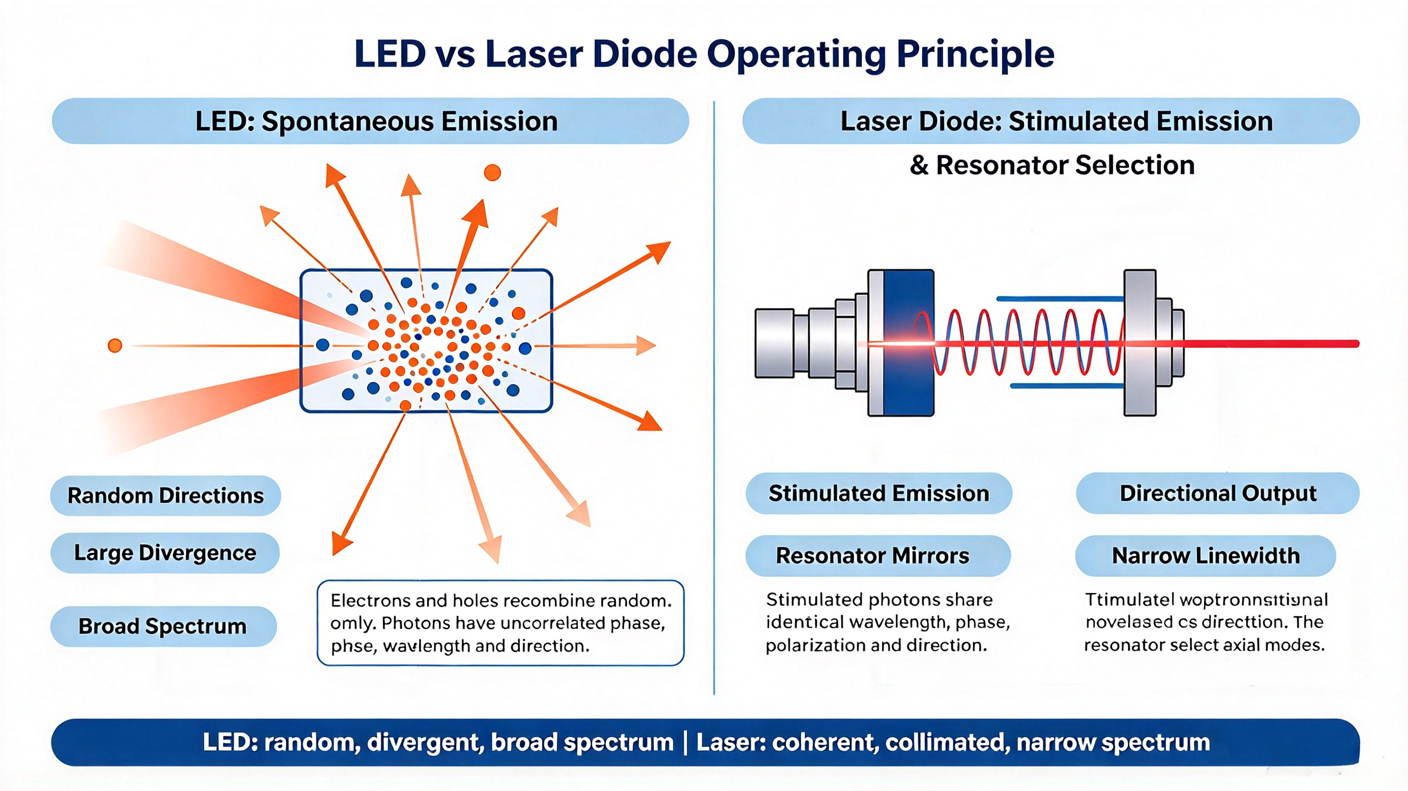
It is critical to separate laser diodes from light-emitting diodes, as this distinction underpins all system design decisions. An LED works purely on spontaneous emission. When electrons and holes recombine in the active region, photons are released randomly, with random phase, propagation direction and wavelength spread. The output beam has a large divergence angle, poor collimation and broad spectral width.
A laser diode operates on stimulated emission above its threshold current. When an incoming photon interacts with an excited electron-hole pair, it triggers recombination and produces a second photon identical in wavelength, phase, polarization and propagation direction. This creates coherent light. The resonant cavity filters out all off-axis photons and amplifies only light traveling along the cavity axis. The final output features narrow linewidth, high directionality, tiny focused spot size and high optical power density.
This coherent property is the reason laser diodes support long-distance ranging, high-speed optical modulation and interferometric sensing, capabilities that regular LEDs cannot achieve.
Internal Epitaxial Structure & Packaging Architecture of Laser Diodes
The term “laser diode structure” covers two separate layers: the epitaxial wafer structure grown on a semiconductor substrate, and the external packaging assembly that holds the chip, optical feedback photodiode and protective components.
Epitaxial Wafer Structure Classification
The evolution of laser diodes is driven by improvements in epitaxial design, which directly determines threshold current, maximum output power, wavelength and temperature stability.
Homojunction Laser DiodeThe P-type and N-type cladding layers use the same semiconductor material. The carrier confinement effect is weak, so threshold current density is extremely high. These devices require cryogenic cooling for lasing and are no longer used in commercial products, mainly reserved for academic research.
Single Heterojunction (SH) Laser DiodeOnly one heterojunction interface is formed between different semiconductor materials. It provides partial carrier confinement but still suffers high threshold current and poor thermal performance.
Double Heterojunction (DH) Laser DiodeTwo heterojunction boundaries sandwich the thin active layer. The difference in bandgap and refractive index traps both charge carriers and optical field inside the active region. Threshold current drops dramatically compared with homojunction and SH designs. DH lasers were the mainstream commercial solution before quantum well technology matured.
Quantum Well (QW) Laser DiodeThe active region is shrunk down to a nanometer-scale ultra-thin quantum well layer. Quantum confinement changes the energy band structure, delivering far lower threshold current, higher slope efficiency, better spectral purity and superior high-temperature performance. Today, nearly all commercially available laser diodes for sensing, communication and indication adopt quantum well epitaxy. Multiple quantum well (MQW) designs stack several quantum wells to further boost output power.
Silicon is not suitable as a gain medium for laser diodes. Silicon has an indirect bandgap, meaning electron-hole recombination mostly releases heat rather than photons. Commercial laser diode materials are direct-bandgap compound semiconductors, including AlGaAs (infrared), InGaAlP (red), InGaN (blue, violet, UV) and ZnO. The choice of material system locks the central emission wavelength of the chip.
Standard TO-Can Packaging Internal Composition
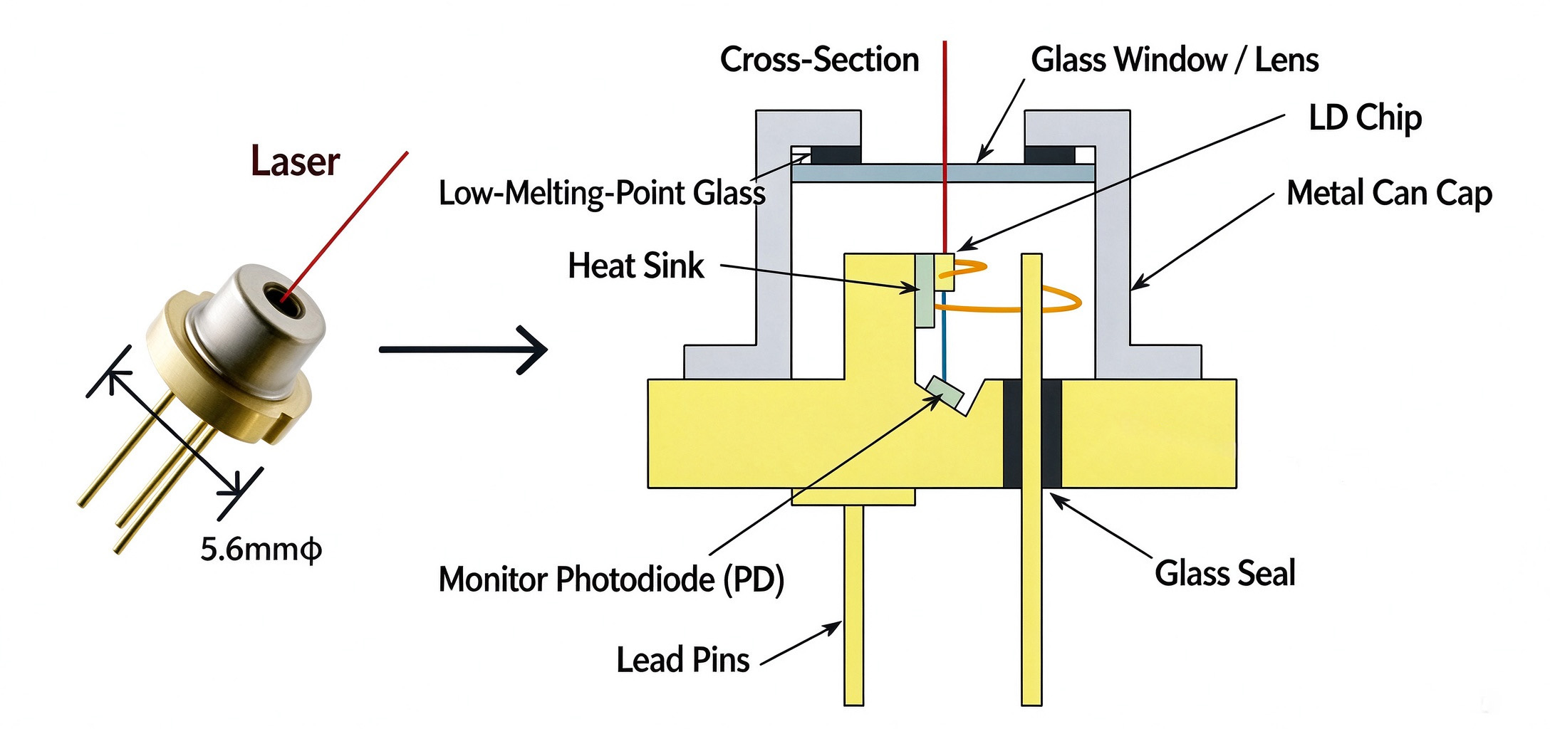
The most common form factor for low and medium power laser diodes is the TO metal can package, often integrating a back-face monitor photodiode (PD). The assembly contains four core sub-components:
LD Laser Chip: The gain medium where stimulated emission takes place. Cleaved facets of the semiconductor crystal act as the resonant cavity mirrors; one facet is high-reflection coated, the other is anti-reflection or partial-reflection coated for light output.
Monitor Photodiode (PD): Mounted behind the laser chip. It captures a small fraction of backward-emitted laser energy and converts optical power into photocurrent signal for closed-loop power feedback. Not all laser packages include a PD; simple indicator laser diodes may omit this feedback device to reduce cost. LD and PD share a common cathode or anode, creating the typical 3-pin pinout.
Glass Window / Collimating Lens: The optical cap seals the cavity against moisture and particulate contamination. Some packages integrate a molded aspheric lens to pre-collimate the raw diverging beam from the chip.
Metal TO Header & Housing: Provides mechanical support, electromagnetic shielding and thermal conduction. High-power single-emitter laser diodes are often packaged in C-mount or butterfly packages for enhanced heat dissipation. Butterfly packages are widely used for fiber-coupled communication laser diodes.
Working Principle of Laser Oscillation & Threshold Characteristics
Laser oscillation builds in a clear sequence once forward bias is applied to the PN junction. When forward voltage is applied, electrons from the N-cladding layer and holes from the P-cladding layer are injected into the active region of the heterostructure. Below threshold current, spontaneous emission dominates. Photons are generated randomly, and optical gain cannot overcome internal absorption, scattering and mirror loss. At this stage, the component behaves like a dim LED.
As the driving current increases, carrier density in the active region rises until population inversion is achieved. Population inversion means more electrons occupy high-energy excited states than low-energy ground states, which is the prerequisite for net stimulated emission.
When optical gain exceeds total cavity loss, the threshold condition is satisfied. Photons traveling along the resonant cavity bounce repeatedly between the two reflective end facets. Each pass through the active layer triggers more stimulated emission. Photons that do not align with the cavity axis escape and are lost; only on-axis photons are amplified coherently. After thousands of round trips inside the cavity, stable, monochromatic laser output is formed from the partially reflective output facet.
Above threshold, the relationship between injection current and output optical power is approximately linear. This linear region is the normal operating window for laser diodes and enables direct high-speed current modulation. This is a core advantage for optical communication and scanning applications.
A critical side effect: laser diode performance is strongly temperature-dependent. Rising junction temperature increases threshold current and reduces slope efficiency. Without thermal control, optical power will drift, and thermal runaway can permanently destroy the chip.
Laser Diode Driver Design, Constant Current and APC Control Topologies
Laser diodes are extremely sensitive to overcurrent, voltage surges and electrostatic pulses. Unlike resistive loads, their I-V curve is very steep. Small voltage fluctuations can produce massive current spikes that burn the active region instantly. Voltage source driving is never recommended for reliable long-term operation.
Constant Current Drive (ACC: Automatic Current Control)
Constant current drivers supply fixed injection current regardless of minor voltage changes across the laser diode. Classic implementations use linear regulators such as LM317 or dedicated laser driver ICs. ACC is suitable for applications where fixed current is preferred, such as pulsed laser systems or low-cost laser pointers. Limitations of ACC: As the laser diode ages or temperature rises, its optical output power drifts, because aging increases internal cavity loss. ACC cannot compensate for power decay over time.
APC Auto Power Control Drive (Closed-Loop Control)
APC is the preferred solution for most industrial and optical communication applications. The built-in monitor PD continuously samples backside optical power and feeds photocurrent to the control loop. The driver circuit dynamically adjusts the forward injection current to maintain constant output optical power.
APC automatically compensates for temperature drift and gradual laser diode aging. Even when the threshold current rises after thousands of operating hours, the loop will raise drive current to hold target brightness stable. Laser rangefinders, barcode scanners and optical pickup units almost exclusively use APC driving circuits.
Essential Protection Circuits
Current-limiting resistor: Restricts maximum forward current as a basic safeguard.
High-speed bypass capacitor: Suppresses fast voltage spikes and ESD transients.
Anti-parallel fast recovery diode: Blocks reverse voltage, preventing junction breakdown.
Thermal shutdown: Integrated temperature sensor cuts off drive current when junction temperature exceeds rated limit.
Laser Diode Wavelength Classification and Typical Material Systems
Emission wavelength is one of the primary selection parameters for buyers, determined by the bandgap energy of the active semiconductor material:
405 nm Violet (InGaN): UV curing, fluorescence excitation, Blu-ray optical storage, spectroscopy
450 nm Blue (InGaN): Laser projection, underwater communication, biomedical imaging
520 nm Green (InGaN): Laser indication, display, visible light sensing
635 nm / 650 nm Red (InGaAlP): Barcode scanning, laser alignment, optical pointer
780 nm / 808 nm Infrared (AlGaAs): Pump source for solid-state lasers, infrared illumination
905 nm Infrared (AlGaAs): Automotive LiDAR, long-range laser ranging
980 nm Infrared (AlGaAs): Fiber amplifier pump laser
1310 nm / 1550 nm Infrared (InGaAsP): Single-mode fiber optical communication, telecom transceivers
Different wavelengths have distinct atmospheric absorption, eye safety classification and optical interaction characteristics with target materials. For example, 905 nm is widely adopted for LiDAR because silicon photodetectors have high responsivity at this band; 1550 nm enjoys superior eye safety threshold for high-power outdoor ranging.
Common Failure Modes, Screening Methods and Reliability Testing
Laser diodes can fail gradually or catastrophically. Many failures are invisible visually, only detectable through electrical and optical testing.
Gradual Degradation
Long-term operation creates defects in the active region and cavity facets. Threshold current slowly increases, and slope efficiency drops. Under APC mode, the driver will keep raising current until the limit is reached, at which point the laser can no longer maintain rated power.
Catastrophic Optical Damage (COD)
High optical power density on the output facet causes local melting of the semiconductor crystal. COD is one of the most common failure modes for high-power laser diodes, often triggered by overdriving, poor heat sinking or surface contamination on the output window.
ESD Damage
Electrostatic discharge can create tiny destructive paths through the PN junction. ESD damage may be latent: the laser still lases at first, but performance degrades rapidly under load. All handling requires anti-static wrist straps, ESD-safe trays and grounded workstations.
Practical Benchtop Screening Methods
Forward and reverse resistance test with high-resistance range multimeter: This is a quick preliminary check. A healthy laser diode has a defined forward resistance range and infinite reverse resistance. A forward resistance that drifts far above the nominal range signals degradation. This method cannot replace optical power testing, because some devices with normal resistance still suffer poor optical output.
I-P (Current-Power) curve testing: The gold standard for characterization. Engineers sweep drive current and record output optical power to extract threshold current and slope efficiency. Comparing the I-P curve against the datasheet reveals facet damage, aging or poor packaging alignment.
Dynamic current monitoring under APC operation: If the control current keeps climbing continuously under fixed target power, the laser diode is undergoing accelerated aging.
Application Segmentation by Optical Function and Industry
The unique optical properties of laser diodes — collimated beam, tiny focused spot, monochromatic spectrum and coherent interference capability — enable seven core functional categories. Each function maps to a wide array of vertical industries.
表格
| Core Function | Optical Characteristic | Representative Industry Applications |
|---|---|---|
| Optical Signal Reading | Micro focused spot for high-speed photoelectric sampling | BD / DVD / CD optical pickups, optical disc read heads, confocal microscopy scanning |
| Optical Recording | High local optical power induces phase change or photochemical reaction | Phase-change optical disc recording, direct laser lithography, photoresist exposure |
| Photographic Exposure | Modulated laser beam patterns latent electrostatic images | Laser printer photoreceptor exposure, multi-function MFP, digital copier engine |
| High-Speed Optical Communication | Direct high-frequency current modulation, high bandwidth | Short-distance free-space optical communication, fiber optical transceivers, data center interconnects |
| Precision Positioning Illumination | Compact point source with stable beam direction | Laser level, alignment marker, machine vision positioning, laser microscope illumination |
| Distance & Displacement Measurement | Low atmospheric attenuation for long propagation | Automotive LiDAR, road survey rangefinders, building height monitoring, industrial displacement sensors |
| Interferometric Sensing | Generates stable interference fringes to capture micro deformation | Dust concentration monitoring, smoke optical sensors, laser mouse tracking, vibration interferometers |
Beyond this classification, laser diodes serve laser medical treatment, laser plastic welding, additive manufacturing, stage lighting, and AR/VR light engine systems.
Critical Design & Handling Best Practices
Eye Safety Compliance: Always confirm the laser class (Class 1, 2, 3B, 4). Direct exposure to Class 3B and Class 4 laser radiation can cause permanent retinal injury. Integrate interlock protection for high-power modules.
Thermal Design Priority: Junction temperature is the dominant factor for service life. Calculate thermal resistance of the package and heat sink; derate operating current for high ambient temperature environments.
Drive Circuit Matching: Match ACC or APC topology according to the application life requirement. For long-lifetime sensing products, APC is strongly recommended.
Storage Condition: Store laser diodes in dry, ESD-controlled environments. Avoid moisture ingress that causes facet corrosion.
Beam Collimation Design: Raw laser diode output has large divergence (fast axis and slow axis asymmetry). Aspheric lenses or cylindrical lens arrays are required to shape the beam for your optical system.
FAQ
Q1:What is population inversion in a laser diode?
Population inversion is a non-equilibrium carrier state where more electrons stay in high-energy excited states than ground states. It is the fundamental prerequisite for stimulated emission to exceed spontaneous emission and achieve optical gain. Normal thermal equilibrium cannot form population inversion.
Q2:What is the difference between single-mode and multi-mode laser diodes?
Single-mode laser diodes support only one transverse optical mode. They feature narrow linewidth, good beam quality and are used for fiber communication and interferometry. Multi-mode laser diodes have wider active regions, higher output power but poorer beam quality, commonly used for pumping, illumination and ranging.
Q3:Why do laser diodes have fast axis and slow axis divergence?
The laser diode active region is a very thin rectangular waveguide. Beam divergence is much larger along the thin vertical direction (fast axis) than the horizontal wide direction (slow axis). This asymmetric beam shape is a unique feature requiring beam shaping optics.
Q4:Can I use a laser diode without a PD monitor diode?
Yes. If you use constant current driving and do not need closed-loop power stabilization, a PD-less laser diode works. The tradeoff is that optical power will drift as temperature changes and the chip ages.
Q5:What is COD (Catastrophic Optical Damage)?
COD is an irreversible failure. Excessive optical intensity on the output facet melts the semiconductor material, creating permanent defects. It is the main failure mode when laser diodes are overdriven or operated without adequate cooling.
Q6:Which laser diode wavelength is safest for outdoor LiDAR?
1550 nm infrared laser diodes have a much higher maximum permissible exposure limit compared to 905 nm, delivering better eye safety for high-power outdoor LiDAR systems.
English
Name*
phone number/ Whatsapp / Wechat*
Email
message*